What are Electrical Substations?

Electrical substations play a critical role in the transmission and distribution of electricity, acting as pivotal points where voltage levels are transformed from high to medium or low and directing the flow of electrical energy to various destinations. An electrical substation comprises a complex network of equipment, including transformers, circuit breakers, and disconnectors, all designed to efficiently manage the power supply to homes, businesses, and industries.
Given the critical role substations play in the electrical grid, maintaining them is not just about preventing downtime; it's about safeguarding the backbone of modern society's energy needs.
What is Electrical Substation Maintenance?
Let’s get right into electrical substation maintenance, and what's included.
Electrical substation maintenance refers to the systematic and routine activities carried out to ensure the proper functioning, reliability, and safety of electrical substations. Substations play a crucial role in the power distribution network by transforming and distributing electrical energy from high voltage to low voltage or vice versa.
Maintenance activities for electrical substations are essential to prevent equipment failures, minimize downtime, and extend the lifespan of the substation components. Here are some key aspects of electrical substation maintenance:
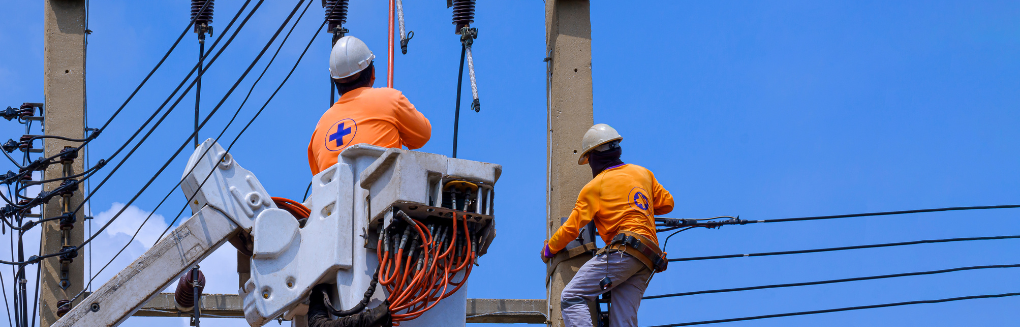
- Inspection and Testing: Regular visual inspections and testing of substation equipment are performed to identify any signs of wear, damage, or potential issues. This includes checking circuit breakers, transformers, switchgear, relays, and other components.
- Cleaning: Dust, dirt, and debris can accumulate on electrical equipment, affecting its performance and insulation properties. Cleaning involves removing these contaminants to maintain proper insulation and prevent overheating.
- Lubrication: Moving parts in various substation components, such as circuit breakers and disconnect switches, may require lubrication to ensure smooth operation and reduce friction.
- Electrical Testing: Various electrical tests are conducted to assess the insulation resistance, dielectric strength, and overall electrical integrity of the equipment. This helps in identifying potential faults before they lead to failures.
- Calibration: Instruments and protective relays in the substation need to be calibrated regularly to ensure accurate readings and proper operation.
- Thermographic Inspection: Infrared thermography is used to detect overheating in electrical components. Hotspots may indicate issues with connections or insulation and addressing them promptly can prevent equipment failures.
- Oil Analysis: For oil-filled equipment like transformers, regular oil analysis is performed to assess the condition of the insulating oil and identify any signs of deterioration or contamination.
- Emergency Preparedness: Maintenance also involves ensuring that the substation is prepared for emergency situations. This includes testing backup power systems, verifying the functionality of protective relays, and having contingency plans in place.
- Record Keeping: Maintaining accurate records of maintenance activities, test results, and equipment history is crucial for tracking the performance of the substation over time and planning future maintenance.
Regular and proactive maintenance helps prevent unexpected outages, ensures the safety of personnel, and contributes to the overall reliability of the power distribution system and can be cost saving. It is typically conducted in accordance with industry standards, manufacturer recommendations, and regulatory requirements.
Why Perform Electrical Substation Maintenance?
Performing electrical substation maintenance is essential for several reasons, all of which contribute to the reliability, safety, and efficiency of the power distribution network. Here are some key reasons to conduct regular maintenance on electrical substations:
-
Prevention of Failures:
Regular
maintenance helps identify and address potential issues before they escalate
into failures. This proactive approach minimizes the risk of unexpected outages
and disruptions to the power supply.
-
Enhanced Reliability:
Maintenance
activities contribute to the overall reliability of electrical substations by
ensuring that equipment operates within specified parameters. Well-maintained
substations are less prone to breakdowns and provide a more stable power
supply.
-
Prolonged Equipment Life:
Regular
maintenance helps extend the lifespan of substation components such as
transformers, circuit breakers, and switchgear. By addressing wear and tear,
cleaning, and performing necessary repairs, the equipment can continue to
operate efficiently over an extended period.
-
Safety Assurance:
Maintenance
activities include inspections of safety systems and equipment. Ensuring that
protective devices, alarms, and emergency response mechanisms are in working
order enhances the overall safety of the substation for both personnel and the
surrounding community.
-
Compliance with Regulations:
Electrical
substations are subject to various regulations and standards that mandate
regular inspections and maintenance. Compliance with these standards is
necessary to ensure the substation meets safety and operational requirements
set by regulatory authorities.
-
Optimized Performance:
Regular
maintenance helps optimize the performance of substation equipment. This
includes calibration of instruments, adjustments to control systems, and
ensuring that all components operate at their designed efficiency.
-
Energy Efficiency:
Properly
maintained equipment operates more efficiently. For example, clean and
well-lubricated components experience less friction, leading to reduced energy
losses. This contributes to overall energy efficiency in the power distribution
system.
-
Cost Savings:
While
there is an upfront cost associated with performing maintenance, it is
generally more cost-effective than dealing with the consequences of equipment
failures. Unplanned outages and emergency repairs can be expensive and lead to
significant downtime.
-
Environmental Impact:
Well-maintained
electrical substations are less likely to experience oil leaks, gas emissions,
or other environmental hazards associated with equipment failures. This
contributes to environmental sustainability and compliance with environmental
regulations.
- Technology Upgrades: Regular maintenance provides an opportunity to assess the condition of equipment and consider technology upgrades. Upgrading to newer, more efficient technologies can improve the overall performance and reliability of the substation.
In summary, performing regular electrical substation maintenance is crucial for preventing failures, enhancing reliability, ensuring safety, and optimizing the performance of the power distribution system. It is a proactive approach to managing and maintaining critical infrastructure that ultimately benefits both the utility providers and the consumers.
What are the preferred service schedules for electrical substations?
Electrical substations may be serviced according to annual or bi-annual cycles
Annual Service Cycle:
- Step 1: Site visit to complete Visual Inspection, thermographic scan and collect oil sample.
- Step 2: Sent Oil sample of for analysis.
- Step 3: Combine thermographic scan and Oil report and share result with costumer and make recommendation to improve electrical system.
Bi-Annual Service Cycle:
- Step 1: Site visit to complete Visual Inspection, Oil sample and Thermographic/ Ultrasonic scan
- Step 2: Sent Oil sample of for analysis.
- Step 3: Complete Thermographic scan report and combine with Oil sample report and make customer aware of any defects or abnormalities.
- Step 4: Complete substation maintenance and fix any previously noted defects or abnormalities and any issues on the day of the maintenance.
- Step 5: Complete Substation maintenance report and share result with costumer and make recommendation to improve electrical system.
What inspections/tests are included for in an Electrical Substation Maintenance?

Electrical substation maintenance involves a variety of tests and inspections to ensure the proper functioning, safety, and reliability of the substation components. The specific tests conducted may vary based on the type of equipment, the substation's configuration, and industry standards. Here are some common electrical tests included in electrical substation maintenance:
-
Visual Inspection:
A visual inspection of all substation components is the first step in
maintenance. This includes checking for signs of physical damage, loose
connections, corrosion, and any abnormalities.
-
Thermographic
Inspection:
Infrared thermography is used to
identify hotspots in electrical components, indicating potential issues such as
loose connections or overloaded circuits.
-
Oil Analysis (for
Oil-Filled Equipment):
For transformers and other
oil-filled equipment, oil analysis is conducted to assess the condition of the
insulating oil and identify potential problems like contamination or
degradation.
-
Grounding System
Inspection and Testing:
Checks the integrity of the
substation's grounding system, including ground resistance testing and
examination of grounding connections.
- Oil filled Transformer Test: This includes various test such as:
-
- Insulation Resistance Test: This test measures the insulation resistance of various components, such as cables, transformers, and circuit breakers. Low insulation resistance can indicate the presence of moisture, dirt, or deteriorating insulation.
- Dielectric Strength (Hipot) Test: The dielectric strength test assesses the ability of insulation to withstand high voltages. It involves applying a higher-than-normal voltage to the equipment to check for breakdown or flashovers.
- Power Factor Test: Power factor testing evaluates the efficiency of insulation by measuring the power factor of the equipment. An increase in power factor may indicate deteriorating insulation.
-
Transformer Turns
Ratio (TTR) Test:
TTR testing is conducted on
transformers to verify the turns ratio and identify any winding issues or turns
discrepancies that could affect performance.
- High and low voltage Disconnect switches or Circuit Breaker Testing: This includes various tests such as:
-
- Contact Resistance Test: Ensures proper electrical connections within the circuit breaker.
- Timing Test: Verifies the operating times of the circuit breaker for proper coordination.
-
Insulation Resistance
Test:
Checks the insulation integrity of the circuit
breaker.
-
Protective Relay
Testing:
Verifies the proper functioning of protective
relays, ensuring they respond appropriately to abnormal conditions.
-
Battery System
Testing:
Verifies the condition of the backup battery
systems used for control and protection. This may include capacity testing and
checking the charging system.
-
Voltage and Current
Measurements:
Routine measurements of voltage and
current help ensure that the electrical parameters are within acceptable
limits.
-
Partial Discharge
Testing:
Detects partial discharges in insulation, which
can be indicative of potential insulation breakdown.
- Load Bank Testing: For generators and other power sources, load bank testing simulates real operating conditions to ensure the equipment functions correctly under load.
It's important to note that these tests are conducted in accordance with industry standards, manufacturer recommendations, and regulatory requirements. The frequency of maintenance and testing depends on factors such as equipment type, age, and criticality. Regular and well-documented maintenance activities contribute to the overall reliability and safety of the electrical substation.
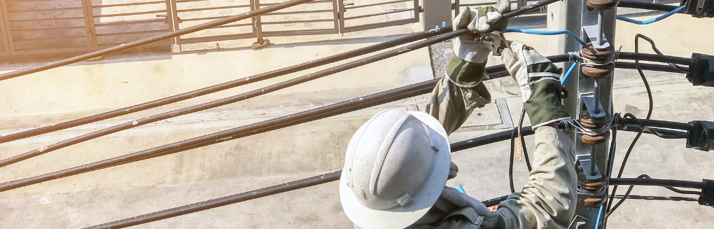
Visual Inspection

Visual inspection is a critical aspect of substation maintenance, It provides an initial assessment of the overall condition of the substation equipment structures and the general site. This inspection is typically conducted by well trained qualified personnel who visually examine various parts of the substation to identify signs of wear, damage, potential theft , vegetation growth, the state of the substation gravel and mechanical protection or potential issues. Here are key aspects of a visual substation inspection:
-
General Site Inspection:
Evaluate the overall condition of the substation site, including the fencing,
access points, and landscaping. Ensure that there are no unauthorized personnel
or animals within the vicinity.
-
Security Measures:
Check the security measures in place, such as locked gates and surveillance
cameras, to prevent unauthorized access and ensure the safety of the
substation.
-
Structural Integrity:
Inspect the structural integrity of buildings, towers, and support structures
(hydro poles) within the substation. Look for signs of corrosion, rust, or
other forms of deterioration.
-
Grounding System:
Examine the grounding system, including ground rods and conductors, to ensure
proper grounding. A well-maintained grounding system is essential for safety
and electrical performance.
-
Fencing and Signage:
Check the condition of the perimeter fencing and signage. Ensure that the
fencing is intact and that warning signs are visible, providing clear
information about the potential dangers of entering the substation.
-
Equipment Condition:
Perform a visual inspection of individual substation components, including
transformers, circuit breakers, switchgear, disconnect switches, and other electrical
equipment. Look for signs of overheating, leaks, corrosion, or physical damage.
-
Insulator Inspection:
Inspect insulators for cracks, contamination, or other issues that could affect
their insulating properties. Damaged insulators may compromise the integrity of
the electrical system.
-
Conductor and Busbar Inspection:
Examine conductors and busbars for signs of corrosion, loose connections, or
damage. Proper electrical conductivity is crucial for efficient power
transmission.
-
Oil-Filled Equipment Inspection:
For oil-filled equipment such as transformers, visually check for oil leaks,
discoloration, and the overall condition of the oil. A well-maintained
oil-filled system is essential for efficient cooling and insulation.
-
Environmental Considerations:
Assess the substation environment for potential issues such as vegetation
overgrowth, accumulation of debris, or the presence of animals. Ensure that the
substation is free from conditions that could compromise safety or equipment
performance.
-
Emergency Response Equipment:
Verify the presence and condition of emergency response equipment, such as fire
extinguishers and first aid kits. Ensure that personnel have access to
necessary safety gear.
- Record Keeping: Maintain records of the visual inspection findings. This documentation is valuable for tracking the condition of the substation over time and planning future maintenance activities.
Transformer oil Analysis
Transformer oil analysis is a diagnostic technique used to assess the condition of the insulating oil in power transformers. The insulating oil in transformers serves multiple purposes, such as providing insulation, cooling, and suppressing corona discharge. Over time, the oil can degrade due to various factors, including oxidation, contamination, and thermal stress. Transformer oil analysis helps in monitoring the health of the transformer and identifying potential issues before they lead to equipment failure.

Key parameters analyzed during transformer oil analysis include:
-
Dielectric Strength:
This measures the insulating properties of
the oil. A decrease in dielectric strength may indicate the presence of
contaminants or degradation of the oil.
-
Moisture Content:
Excessive moisture in transformer oil can
lead to a decrease in dielectric strength and accelerate the aging of the
insulation. Moisture is typically measured in parts per million (ppm).
-
Acidity:
The acidity of the oil is an indicator of the
degree of oxidation. Increased acidity suggests that the oil is breaking down
chemically, which can impact the transformer's insulation.
-
Power Factor:
Power factor is a measure of the dielectric
losses in the insulation system. An increase in power factor may indicate the
presence of contaminants or deterioration of the insulation.
-
Dissolved Gas Analysis (DGA):
This involves analyzing the gases dissolved in the transformer oil. The
presence and concentration of specific gases, such as methane, ethane,
acetylene, and hydrogen, can provide insights into potential issues, such as
overheating, partial discharge, or arcing within the transformer.
-
Furan Analysis:
Furan compounds are formed during the thermal
degradation of cellulose insulation. Furan analysis can help assess the
condition of the solid insulation in the transformer.
-
Interfacial Tension:
This measures the cleanliness of the oil and can indicate the presence of
contaminants.
- Color and Appearance: Visual inspection of the oil for changes in color or appearance can reveal contamination or degradation issues.
Transformer oil analysis is typically part of a comprehensive predictive maintenance program for power transformers. Regular monitoring and interpretation of the test results allow maintenance professionals to identify potential problems early, schedule maintenance or repairs, and extend the life of the transformer. It is important to follow industry standards and guidelines for sampling and analysis and to compare results against established benchmarks for the specific transformer and oil type.
Thermographic imaging
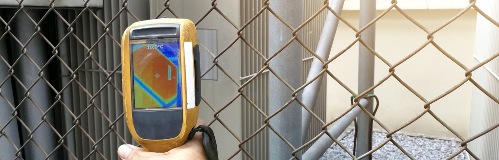
Thermographic imaging is widely used in electrical systems for preventive maintenance and troubleshooting. The application of thermography in electrical inspections involves using infrared cameras to detect and visualize temperature variations in electrical components. Here's how thermographic imaging is utilized in electrical systems:
-
Identifying Hotspots:
Thermographic
imaging is particularly useful for identifying hotspots in electrical
components, such as circuit breakers, fuses, switches, and electrical panels.
Hotspots may indicate problems like loose connections, overloaded circuits, or imbalanced loads, all of which can lead to electrical failures or fires.
-
Preventive Maintenance:
Regular thermographic inspections of
electrical equipment are part of preventive maintenance programs. By detecting
potential issues early, maintenance personnel can address problems before they
escalate, reducing the risk of unplanned downtime and equipment damage.
-
Loose Connections:
Loose electrical connections can create resistance and generate heat.
Thermographic imaging helps identify loose connections in terminals, bus bars,
and other components.
Early detection of loose connections is crucial for preventing overheating, arcing, and equipment failures.
-
Overloaded Circuits:
Thermography can reveal overloaded circuits by highlighting areas with elevated
temperatures. Overloaded circuits can lead to overheating and pose a fire
hazard.
Monitoring temperature variations allows for the adjustment of loads, or the installation of additional capacity as needed.
-
Phase Imbalance:
Imbalances in current distribution among phases can lead to overheating in
electrical systems. Thermographic imaging helps identify phase imbalances by
detecting temperature variations across phases.
Addressing phase imbalances improves the overall efficiency and lifespan of electrical equipment.
-
Switchgear and Panel Inspections:
Thermography is used to inspect switchgear, distribution panels, and other
electrical enclosures for anomalies. It helps ensure that all components are
operating within safe temperature ranges.
Detecting issues in these components early on prevents equipment failures and extends the life of the electrical infrastructure.
-
Transformers and Motor Inspections:
Thermographic imaging is applied to transformers and electric motors to monitor
their temperature profiles. Overheating in these components may indicate
problems such as insulation breakdown or mechanical issues.
Regular inspections using thermography help identify potential failures before they cause major disruptions.
- Recording and Analysis: Thermographic images are recorded and analyzed over time to track temperature trends and changes in electrical components. This historical data aids in predicting potential issues and planning maintenance schedules.
It's important to note that proper training and interpretation skills are essential for effective thermographic inspections. Professionals performing these inspections should understand the electrical system, know the expected thermal patterns, and be able to differentiate normal operating conditions from potential problems. Regular thermographic surveys of electrical systems contribute significantly to the safety, reliability, and efficiency of industrial and commercial electrical installations.
Electrical Power Study/ Power System Study
Electrical Power Study/ Power System Study Performing an electrical power study, also known as a power system study or electrical power analysis, is crucial for various reasons in the design, operation, and maintenance of electrical power systems. Here are some key reasons why electrical power studies are conducted:
-
System Design and Planning:
Electrical power studies help in designing power systems with the appropriate
capacity, redundancy, and reliability to meet the present and future demands.
These studies aid engineers in determining the optimal configuration of the
power system.
-
Load Flow Analysis:
Load flow studies assess how electrical power flows through a network under
normal operating conditions. This information is essential for optimizing the
distribution of power, ensuring balanced loading, and preventing overloads in
the system.
-
Voltage Drop Analysis:
Voltage drop studies evaluate the voltage levels at various points in the power
distribution system. This is critical for ensuring that electrical devices
receive the required voltage to operate properly and that there are no
excessive voltage drops.
-
Short Circuit Analysis:
Short circuit studies assess the behavior of the power system under fault
conditions. This helps in determining the magnitude of fault currents and
selecting protective devices such as circuit breakers and fuses to safeguard
the system and connected equipment.
-
Protective Device Coordination:
Coordination studies are performed to ensure that protective devices, such as
relays and circuit breakers, are appropriately coordinated to isolate faults
and minimize the impact on the rest of the system. Proper coordination enhances
system reliability and reduces downtime.
-
Arc Flash Hazard Analysis:
Arc flash studies evaluate the potential for arc flash incidents within the
electrical system. This is essential for determining appropriate safety
measures and personal protective equipment (PPE) for personnel working on or
near electrical equipment.
-
Harmonic Analysis:
Harmonic studies assess the presence and impact of harmonics in the power
system. Harmonics can lead to issues such as equipment overheating and
increased losses. Mitigation strategies can be implemented based on the results
of harmonic analysis.
-
Transient Stability Analysis:
Transient stability studies evaluate the system's ability to recover from
transient disturbances, such as sudden load changes or faults. This analysis is
crucial for ensuring the stability and reliability of the power system.
-
Energy Efficiency Optimization:
Power studies help identify opportunities for improving energy efficiency in
the power system. This may involve adjusting operating parameters, upgrading
equipment, or implementing energy-saving technologies.
-
Compliance with Standards and
Regulations:
Electrical power studies ensure that
the power system design and operation comply with industry standards, codes,
and regulations. Compliance is essential for safety, reliability, and legal
requirements.
- Asset Management and Maintenance Planning: By understanding the performance of the power system through studies, maintenance activities can be planned more effectively. This helps in extending the life of equipment and reducing the likelihood of unexpected failures.
In summary, electrical power studies are conducted to optimize the design, operation, and maintenance of power systems. They provide critical insights into the performance, reliability, and safety of electrical networks, allowing for informed decision-making and effective management of electrical infrastructure.
What are the common components of an electrical substation?
Electrical substations play a crucial role in the power distribution network, transforming and distributing electrical energy from high voltage to low voltage or vice versa. Substations consist of various components that work together to ensure the efficient and safe transmission of electricity. The specific components in an electrical substation can vary based on factors such as the type of substation, its purpose, and its location. However, common components found in many electrical substations include:
Main or Primary Feeder:
The High voltage cable where on the primary voltage is transported to the Electrical substation usually owned by the local distribution company. Most common voltage are 44,000V, 27.600V and 13.800V.
The electrical system starts off with a feeder that is owned, operated and controlled by the customer LDC (Local Distribution Company). This feeder is usually brought in overhead on wire or underground through cable.
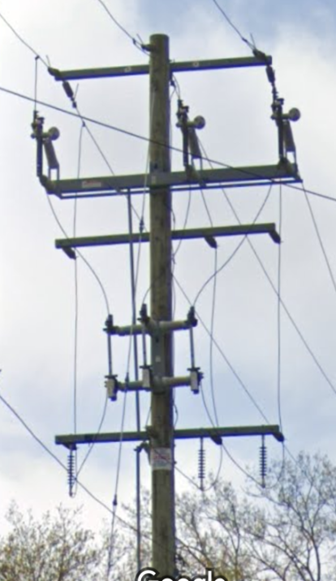
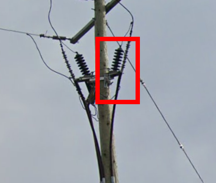
Overhead wire will be mounted on Hydro poles held in place by insulators (Example #1)
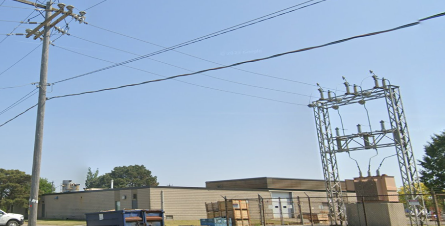
Example #1 - Overhead wires mounted on Hydro poles held in place by insulators
The underground cable will be installed on a hydro pole (Dip pole) mounted down the side transitioning into an underground raceway (Duct bank) (Example #3); the Cables and conduit are usually protected by steel cable guards.
Usually the LDC owned equipment will have markings
on the closest hydro pole (example #2) to identify what equipment is on them or
where in their system this equipment is located this is useful information to
know in conversations for shutting down the electricity to the customers site.
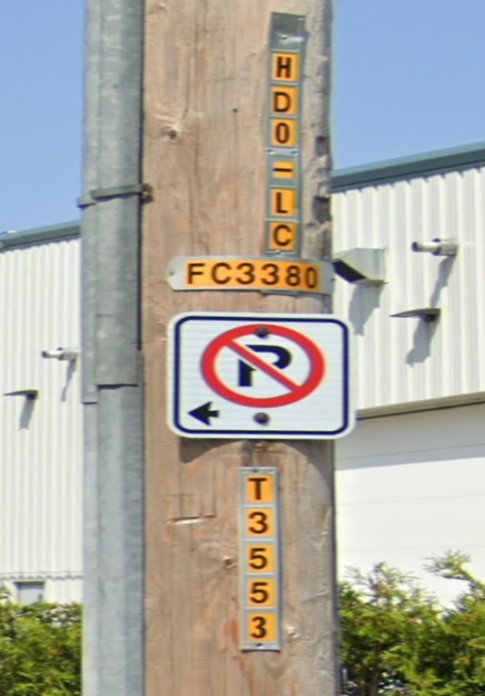
Example #2
LDC-owned equipment markings
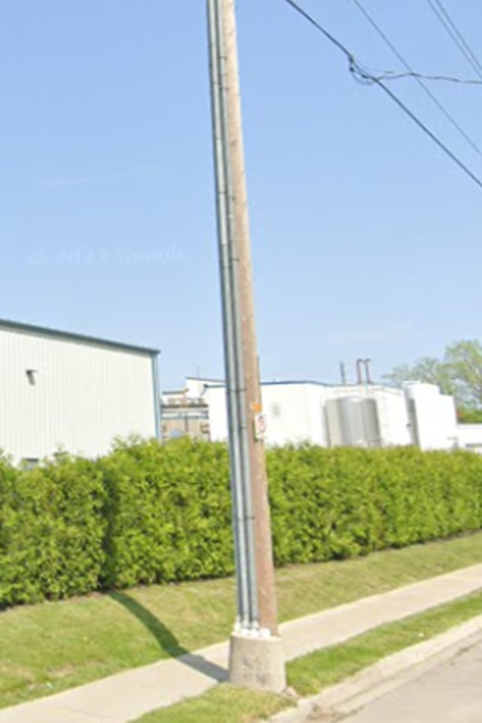
Example #3
Underground cable installed on a hydro pole
Metering:
- Secondary Metering: Secondary metering is the most common from of metering It consists of PT and CT installed on the Load side of the Main disconnect of the Secondary switchboard. The costumers will have a meter socket with a hydro meter installed in close approximation where the secondary electrical service is located that usually is accessible from the outside this possible. This way of collecting data is done on sites that have only one service or multiple services that have different primary feeders.
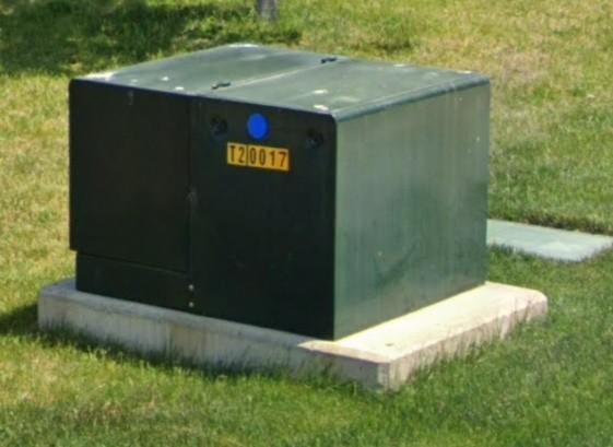
- Main or Primary Metering: Main or Primary metering could exist on a costumer if there is multiple service on site or if there is any renewable source of energy available, always owned and installed by the LDC (Local distribution company) if its installed for revenue metering and not part of the maintenance. If installed to meter for metering renewable source customer installed and customer owned. Most common voltage are 44,000V, 27.600V and 13.800V and can be Pole Mounted (Example #4) or metal enclosed (Metering Cell) (Example #5).
Example #4
Pole-mounted metering
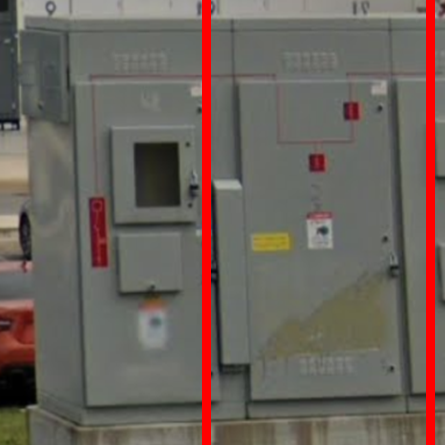
Example #5
Metal enclosed metering cell
Means of Disconnect:
The Main or Primary disconnect is a piece of equipment that will isolate the sub-station from the main or primary feeder. Disconnect can come in many different forms:
- Isolation Switches
-
- Options include, Pole mount, Structure mount and Metal enclosed.
- Circuit Switcher
-
- Most common voltage are 44,000V, 27.600V and 13.800V
- Isolating Switches:
-
- Load Break Switch (LBS): Designed for making and breaking of loaded circuits. They can interrupt the current when the switch is opened and have arc suppressors.
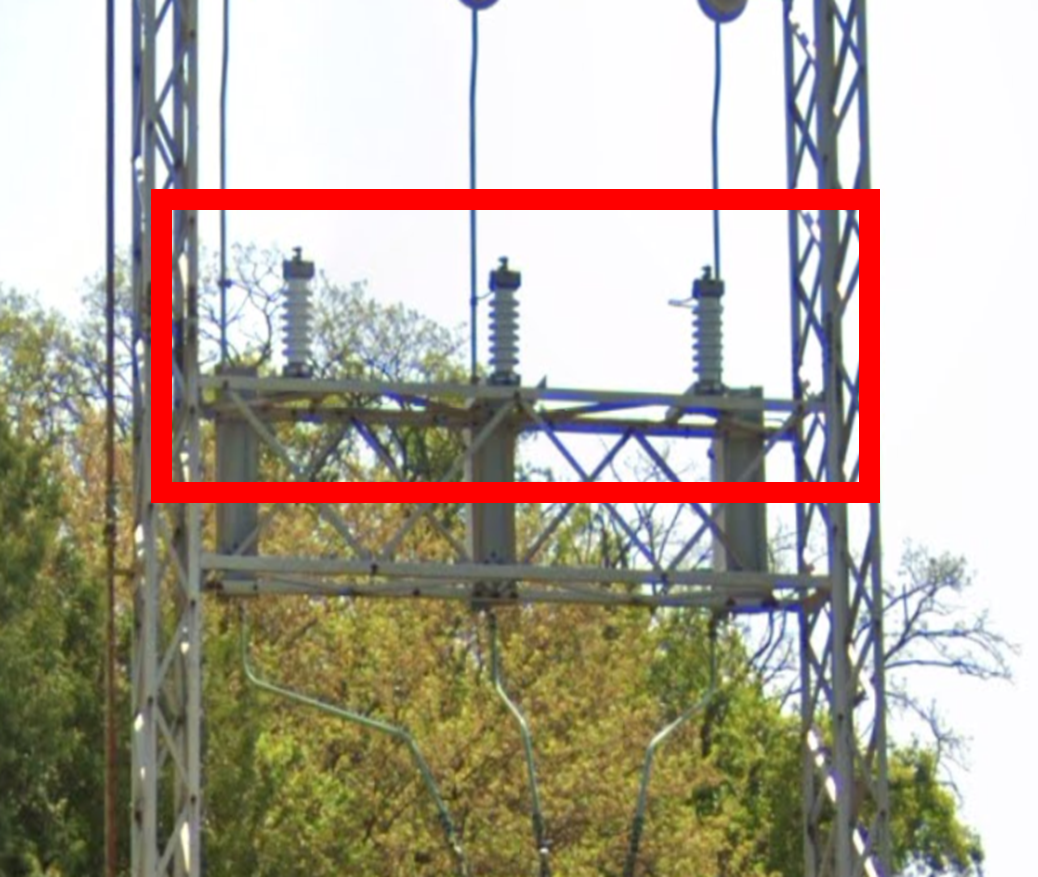
- Air Break Switch: Utilizes air as the interrupting medium, often used in outdoor applications and can not be operated underload, so they are usually accompanied with an interlock scheme.These Switches can be horizontal (Example #6) and vertical (Example #7) pole or Structure mounted (Example #8)
- Metal enclosed: Metal enclosed is the final option (Example #9). These are used if a single customer has multiple services on site with a common point where the LDC is collecting the data (metering point/primary metering) on customer electrical usage.
Example #6
Horizontal Switches
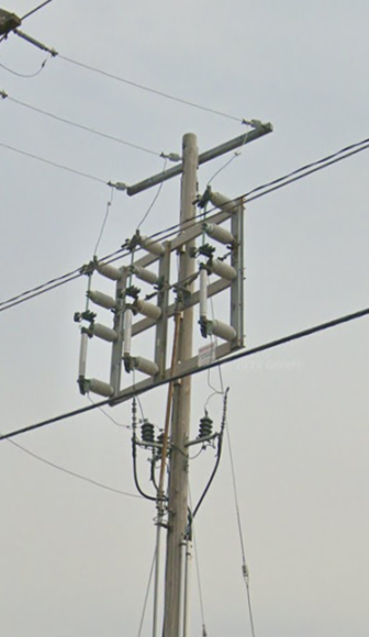
Example #7
Vertical Switches
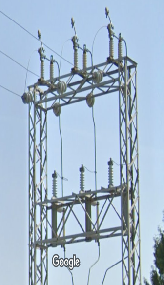
Example #8
Structure Mounted Switches
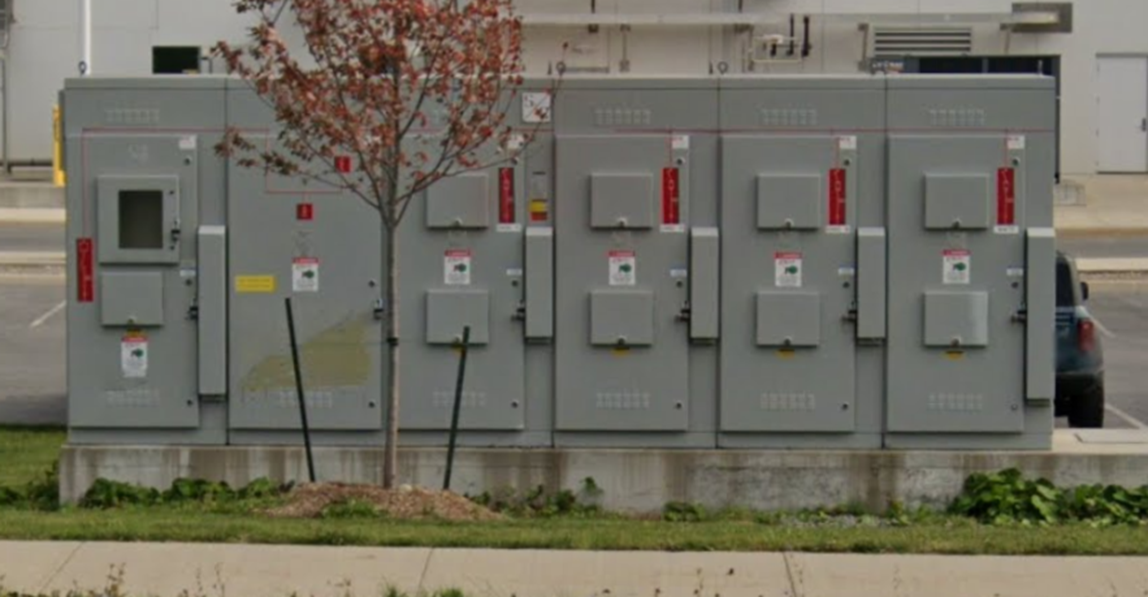
Example #9
Metal Enclosed Switches
Circuit Breakers:
Circuit breakers are devices that interrupt or break the flow of electric current in the event of a fault or overload. They play a crucial role in protecting the electrical system from damage and ensuring the safety of the equipment. Includes protection relays.
- Vacuum Circuit Breaker (VCB): Uses a vacuum as the interrupting medium, providing reliable switching for medium and high voltage applications.
- SF6 Circuit Breaker: Uses sulfur hexafluoride gas as the interrupting medium, commonly used in high-voltage applications. SF6 breakers are usually only found in bigger and more complex electrical substations with higher voltages that require additional protection.
Surge Arrestors:
Surge arresters (LA’s) protect the substation equipment from voltage surges caused by lightning or other transient events. They redirect excess voltage to the ground. They usually come in distribution class or Station class. Older surge arrestors are manufactured out of Porcelain while newer once are usually Polymer (Example #10 and #11).
Example #10
Porcelain Surge Arrestors
Example #11
Polymer Surge Arrestors
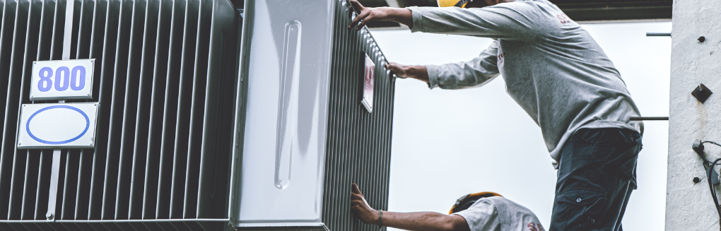
Transformers:
Transformers are essential components that change the voltage level of electrical power. Step-up transformers increase voltage for long-distance transmission, while step-down transformers decrease voltage for distribution to end-users. Transformers can come in many different forms.
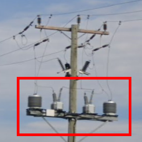
- Pole or structure mount transformer: Usually smaller transformers up to Single Phase 167kV that can be installed as a cluster of three and are always Oil filled (Example #12).
- Ground mount: Any size greater than Single or Three Phase 167kV, can be Oil filled or Dry Type (Example 13).
- Station Class or Tamperproof: The main difference between Station class and tamperproof is Station Class Transformers have exposed electrical parts and require additional barriers to prevent contact with live parts.
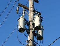
Example #12
Poll-mount transformer
Example #13
Ground-mount transformer (dry type)
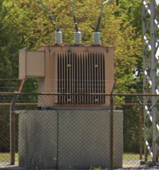
Example #14
Station class transformer
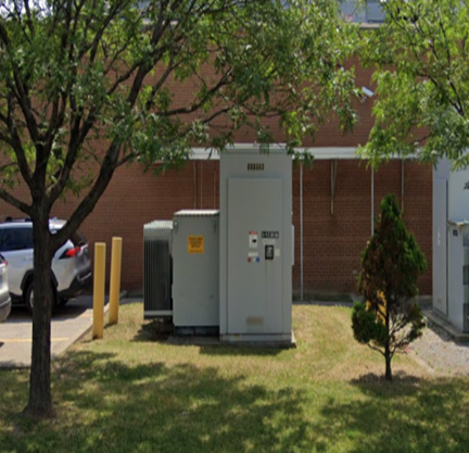
Example 15
Tamper-proof transformer
Configuration of Transformers: Delta/Delta, Delta/Wye and Wye/Wye, Layout of the primary and secondary bushings and internal core connections. Configuration depends on Customer and LDC requirements.
- Delta (Δ) Configuration:
-
- In a delta configuration, the windings are connected in a triangular (delta) shape.
- Each winding is connected to the next one in series, forming a closed loop.
- The line voltage is the same as the phase voltage, and the phase current is the line current.
- The phase angle between the primary and secondary voltages is zero degrees.
- Wye (Y) Configuration:
-
- In a wye configuration, the windings are connected in a Y shape.
- One end of each winding is connected to a common point called the neutral, and the other ends are connected to the three phases.
- The line voltage is √3 times the phase voltage, and the line current is the same as the phase current.
- The phase angle between the primary and secondary voltages is 30 degrees.
Location of Live Parts: (Primary and secondary bushings). Top/Top, Top/Side Side/Side and Dead Front.
Most common Primary voltages: 44,000V, 27.600V and 13.800V
Most common Secondary voltages: 600V, 347V and 208V
Switchgear:
Switchgear includes various switching devices such as switches, disconnectors, and fuses. It allows for the control, protection, and isolation of electrical equipment within the substation.
Disconnect Switches:
Disconnect switches are used to isolate sections of the electrical system for maintenance or in the event of a fault. They provide a way to de-energize specific components without affecting the entire substation always includes fuses.
Capacitor Banks:
Capacitor banks are used for power factor correction to improve the efficiency of the electrical system. They help maintain a balanced and efficient power flow.
Instrument Transformers:
Current transformers (CTs) and voltage transformers (VTs) are instrument transformers that provide reduced and isolated signals for measurement and protection devices. They allow for safe monitoring of current and voltage levels.
Control and Protection Systems:
These systems include relays, control panels, and communication equipment that monitor and control the operation of various components within the substation. They also provide protection against abnormal conditions.
Grounding System:
The grounding system includes ground rods, conductors, and grids that provide a path for fault currents to safely dissipate into the ground. It helps maintain proper safety levels and equipment functionality.
Control Building or Enclosure:
Many substations include a control building or enclosure (E-House) that houses control panels, monitoring equipment, and sometimes personnel for managing and overseeing substation operations.
Battery and Charger Systems:
Batteries and chargers provide backup power for control and protection systems in case of a power outage. They ensure that critical components remain operational during emergencies.
These components work together to transform, distribute, and control electrical power within the substation. The specific configuration and design of a substation depend on factors such as its size, capacity, location, and the purpose it serves in the overall power grid.
What equipment is required to service electrical substations?
- Oil box: Contains all the tools, adaptors, cleaning supplies and containers (syringe, mason Jars and jugs) to perform an oil sample.
- Cleaning supplies: Rags, Abrasive pads, rubbing alcohol, WD40 Lubricant and Cleaning solution preferably specialized for electrical application.
- Grounds: To ensure the System is de-energized and stays de-energized, preferably a set of High Voltage grounds and a couple of sets of low voltage grounds.
- Arc-Flash Gear: To be worn while switching/de-energizing the equipment, including Gloves, Face shield and Jacket or suit.
- Hot stick: Piece of equipment to assist with applying the ground.
- Penta socket: Most Transformer access plates are secured with Penta bolts as specialize socket is required to remove these bolts.
- Voltage Detector: High voltage Detector, Example Amprobe TIC 300 PRO High Voltage Detector Tic Tracer 122kV AC, to detect if the work area is free of any potential.
- Generator: to provide temporary power of test equipment and job site lights.
- Extension cords
- Job Lights: To provide light for the work area.
- Lifting device: Bucket truck or any other device that is deemed suitable for the job of reaching equipment that is elevated.
- Test equipment:
-
- Transformer test equipment
-
- TTR, Transformer turns ratio meter,
- Winding resistance meter:
- Capacitance Bridge:
-
- 10kV Megger
- Additional test equipment:
-
- 1kV Megger
- Contact resistance meter
What documentation is provided after electrical substation maintenance is performed?

After each electrical maintenance is completed, the customer is provided with a detailed copy of all the test results and observations including:
- ESA Substation report
- Oil Sample
- Test Sheets:
-
- High Voltage disconnect data and test heet
- Transformer Data and test sheets
- Circuit breaker Data and test sheet
- Low Voltage Device data and test sheet